

Modelling is at the heart of modern engineering practice. Engineers model things all the time. Models allow engineers to conduct many ‘what if’ experiments and also to study potential failures in the system. While mathematical models have been in use for a long time, in the last few decades, computer models have become indispensable. But one problem remains - the different ways in which engineers from different streams build the models. For example, mechanical engineers usually use CAD models and Finite Element Analysis. Electrical engineers use circuit diagrams, while a computer science engineer may use flow charts and object-oriented modelling in programming.
There have been attempts to bridge this gap, though. One particular solution is the Modelica language, which is for engineering design and simulation. Modelica is a domain neutral language with which small, simple things like resistors, as well as large and complex systems like automobiles and power plants can be modelled.
The Modelica language
Modelica is an object-oriented, equation based modelling language. It is not proprietary, and is managed by the Modelica Association. The purpose of Modelica is to describe engineering components and systems. We cannot think of Modelica as a programming language such as C++ or Java. Modelica needs an implementation environment. It is important to remember this Modelica is a modelling language. Once we have modelled an engineering system, we can run the model and see how the system behaves. For example, if youve built a model of a braking system for a car, you can run the simulation and see how the braking system behaves under different load conditions. Or if you have built a circuit model, when you simulate the model, you can see how current and voltage change with respect to time in different components. Modelica model files have .mo as the extension.
As mentioned earlier, well need to implement an environment for Modelica models to run. There are many such run environments. Some are open source, and some are proprietary. Important run environments for Modelica are OpenModelica, JModelica and Dymola. While OpenModelica and JModelica are free and open source platforms, Dymola is a commercial platform. Personally I would prefer OpenModelica as it is cross-platform, easy to use/install, comes with many other supporting tools, has very good documentation for learning, and has a reasonably good community around it, which is very essential.
Modelicas components library
Modelicas components library is a very powerful feature. As Modelica is an object-oriented modelling language, the idea of re-using components is very naturally exploited. And to make things even more interesting, Modelica Association releases whats in the components library on a free basis. The library is basically a collection of models of the most commonly used engineering components. To be more specific, it contains Blocks (mathematical/logical function blocks), ComplexBlocks, StateGraph, Electrical, Magnetic, Mechanics, Fluid, Media, Thermal, Math, ComplexMath, Utilities, Constants, Icons, and SIunits packages. Each of these packages contain different component models under different sub-sections. Now imagine that you’re building a model of a robotic arm, which contains both electrical and mechanical components, along with control software. You don’t have to build models of components like the motor or shaft. You can just use the available component models in the library, fine tune the model parameters and connect to see how your system works.
OpenModelica
OpenModelica is a platform for the Modelica language. Its free, based on open source software and is supported by the Open Source Modelica Consortium. OpenModelica can be installed both on Linux and Windows platforms. In the OpenModelica package, three important modules are available OMEdit, OMNotebook and OMShell. OMEdit is a graphical interface, which can be used to build models and run simulations. OMNotebook is an innovative learning companion, with which you can read the relevant information on a particular concept and also run the code there itself. While it will not teach you how to use OMEdit, which is a graphical editor, OMNotebook will help you to understand the basics of the Modelica language very clearly and help you build a very strong foundation on the topic. You can download and install OpenModelica for Linux from https://openmodelica.org/download/download-linux, and for Windows from https://openmodelica.org/download/download-windows.
If you face a problem in installing it, you can also download a virtual machine with pre-installed OpenModelica from https://openmodelica.org/download/virtual-machine.
Getting started with OMEdit
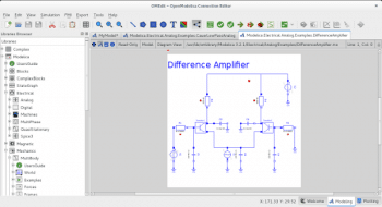
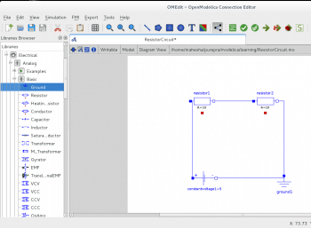
OMEdit is a graphical editor that allows you to access Modelicas components library, which you can see on the left side of the screenshot in Figure 1. Building a model is as easy as dragging and dropping components into the model area, and connecting suitable components. Of course, you should know which components to use, and what the appropriate value for different parameters of the components is. We’ll build a very simple electric circuit to get started with OMEdit. Here are the steps.
1. Start OMEdit.
2. Go to File →New Modelica Class →Name→ResistorCircuit (weve provided model name, not file name).
3. Click on Save →ResistorCircuit.mo [Note: This is the file name].
4. Go to Modelicas components library. Open Electrical→Analog→Basic. Drag and drop resistors into the model area. Double-click, and enter resistor values for both.
5. Similarly, open Electrical→Analog→Sources→Constant Voltage (for batteries).
6. Once the components are in place, and the appropriate parameter values are entered, were ready to connect. To do so, click, drag, and connect from one end of the component to another end.
7. Once all the connections are done, run the simulation. Menu: Simulation→simulate
8. Viewing the results is also very easy. Just click on the Plotting tab in the bottom right corner, and youll see a list of components in a tree. If you expand the tree, you can select the parameter of your choice, and youll be able to see the plotting of that parameter value with respect to time.
While this example used only electrical components, we can easily use mechanical and electrical components in a single model and simulate the operations. I would also recommend that users explore OMNotebook, as it can be a very good learning companion in the beginning.


