In this second article in the series on ‘Evolution of Web protocols’, we follow the development of the HTTP and SSL protocols. We begin with a timeline that depicts the evolution of these protocols.
In the first article in the series carried in the February issue of OSFY, we discussed the evolution of the Web protocol stack since its inception in the 1990s to the present day. The early stack comprised the DNS and HTTP/1.1 application protocols, transported respectively on UDP and TCP, with both the protocols using the services of IP. Both DNS and HTTP were unsecured protocols that could be ‘read’ by anyone with access to either the network path or a copy of the packet flow. As the Internet grew and was found suitable for commercial applications, this lack of security was not acceptable. Hence, a new session layer protocol called SSL, which encrypted all application traffic, was proposed and eagerly adopted, especially for HTTP, giving rise to the now ubiquitous HTTPS. In the first article in this series, we followed this evolution and looked at the key characteristics of the DNS and HTTP protocols.
Now, let us follow the evolution of the HTTP and SSL protocols to their next versions, starting with a timeline that depicts the evolution of these protocols (Figure 1).
As can be seen in the timeline, HTTP/1.1 remained unchanged for a long period of 16 years (from 1999 to 2015). In the interim, its successor started as SPDY within Google, getting deployed within the Google browser and server stacks.
It was then brought to IETF, where it was adopted with relatively minor changes as HTTP2. On the other hand, SSL underwent five revisions between 1995 and 2008, when TLS 1.2 was adopted. TLS 1.2 ruled the Web for a decade before TLS 1.3 was proposed.
 What drives Web protocols to evolve
In today’s world, the Internet is not just a novelty or a luxury – it is a necessity for a significant fraction of the population. For that reason, it needs to be highly available, secure and fast. While higher availability can be addressed by replacing redundant hardware and cabling, security and speed must be built all through the stack, including into the hardware and software. As we discussed in the last article, the network stack is the foundation of the Internet and it implements the protocols that govern network communication. While the early network protocols were focused on ‘getting it right’, the current motivation is to go beyond the functional requirements, and forms the basis for overhauling the protocols for security and performance.
Characteristics of contemporary Web portals
With the emergence of Web 2.0, the nature and quantum of the contents on Web portals changed. We have all experienced that — while the early Web was quite ‘bare’ and text-intensive, today’s portals are much more captivating with images, videos and the unavoidable ads. With more expressive sites, each portal is getting heavier in terms of the number of objects that have to be delivered to the browser. These objects include CSS, images and JavaScript, in addition to the regular HTML files.
For example, when I tried www.flipkart.com from my browser, captured the resultant traffic as a HAR file and analysed it, I observed the following. The browser made a total of 87 HTTP transactions, spread across 10 hosts. The following table summarises my observations (note that conducting the same experiment again may yield slightly different numbers):
www.flipkart.com: 4

rukminim1.flixcart.com : 40
img1a.flixcart.com: 18
1.rome.api.flipkart.com : 16
rome.api.flipkart.com: 3
flipkart.d1.sc.omtrdc.net: 2
desa.fkapi.net : 1
desa.fkapi.net : 1
desr.fkapi.net : 1
dpm.demdex.net : 1

Num hosts = 10
Num txns = 87
Total content = 731550 bytes in 65 non-zero responses
To repeat, just to render the front page of Flipkart, the browser had to make connections with 10 different hosts and triggered 87 HTTP requests, with a maximum of 40 requests to one of the hosts. I also observed that the total content downloaded was approximately 714kB, just to display this page.
I tabulated similar data for the front pages of a few more popular portals to see if this trend remains the same (see Table 1).
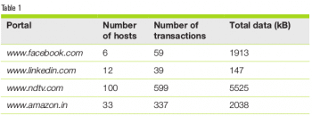 While this is just data from a few portals, it does show that each modern portal triggers multiple connections and HTTP transactions. In fact, the news site is seen to be the most ‘chatty’, followed by the shopping site. While this data set is tiny, it does depict the trend. The current averages of the number of connections and the number of requests per page are 14 and 74, respectively (see https://httparchive.org/reports/state-of-the-web). Let us also be reminded that this is only with the front page of the portal – as one navigates across the portal, more contents will be available, requiring more connections and HTTPS requests/responses.
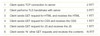
The reader will notice that with so many transactions, the limited concurrency of HTTP/1.1 can be a big challenge in rendering the page quickly. While the browser may not have to wait for every transaction to complete, it may have to wait for data from some of the connections before it can start rendering the page. Typically, it needs to wait for the CSS and JavaScripts to be available before it can render the page. Let us follow one example in detail to get a feel of the sequence. Here we enumerate the step performed by the client (i.e., the browser) and the minimum time taken for that step. To keep things general, it is common to measure time in units of RTT or round trip time, i.e., the time taken for a packet to travel from the client to the server and back.
With an RTT of 25ms, it takes 175ms before the browser completes Step 5 in the table given at the bottom of this page. While this may seem like a very insignificant time duration, research indicates that users are most engaged when the lag is within the range of 500ms; anything greater than 1000ms can cause users to switch their attention to other pages. Of course, this data may be from western consumers and Indians may be more patient, but the RTT from India may also be higher.
As seen here, even after the connection and TLS setup, it takes another 3 RTT to receive the key contents even if the server was ready to serve them all in Step 3. This implies that even if the server had the processing capacity to serve such contents simultaneously, because of protocol limitations, it would still have to process requests in the order they arrived, leading to the additional latency.
Similarly, the TCP and TLS layers also add a minimum of 5 RTT for every connection.
A look at how protocols evolved
Before we get to the actual protocols, let’s look at the new protocols that have been either recently specified or are in the process of being defined. Let us also examine which part of the stack they operate in, bringing in performance improvements.
1. Transport layer: TCP to QUIC
2. Session layer: TLS 1.2 to TLS 1.3
3. Application layer (or layer 7): HTTP 1.1 to HTTP/2 to HTTP/3
In this article, we will be focusing on the design of the HTTP/2 protocol and the performance improvements that it is expected to bring in. We also briefly look at TLS 1.2 as it is the most stable and widely deployed security protocol till date.
Let’s begin by running through the HTTP 1.1 protocol that was covered in the earlier article in this series. HTTP 1.1 follows a simple text-based request/response message format, as shown in the sample transaction below.
HTTP request – sent by client
GET / HTTP/1.1
Host: www.example.com
User-Agent: curl/7.65.0
Accept: */*

HTTP response – sent by server
HTTP/1.1 200 OK
Accept-Ranges: bytes
Cache-Control: max-age=604800
Content-Type: text/html; charset=UTF-8
Date: Sat, 11 Jan 2020 06:30:35 GMT
Etag: “3147526947+ident”
Expires: Sat, 18 Jan 2020 06:30:35 GMT
Last-Modified: Thu, 17 Oct 2019 07:18:26 GMT
Server: ECS (sjc/4E73)
Vary: Accept-Encoding
X-Cache: HIT
Content-Length: 1256

<!doctype html>
<html>
<head>

<title>Example Domain</title>

<meta charset=”utf-8” />
…
The key features of HTTP 1.1 are:
1. Message headers and metadata are sent in text format.
2. Limited message concurrency:
a. In HTTP 1.0, only one message could be sent on a connection. This imposed a connection setup overhead for every transaction and was quickly seen as inefficient.
b. HTTP 1.1 improved on this with persistent connections, i.e., a client could send multiple requests on the same connection.
c. HTTP 1.1 also introduced request pipelining. With this, a client did not have to wait till a response for an earlier request was received before it sent the next request. However, the server still processed one request at a time and in the order in which these were received.
HTTP/2: An overview
As seen earlier, the limited concurrency of HTTP 1.1 causes the browser to wait till earlier requests were responded to, even when the server could have satisfied the requests simultaneously. HTTP/2 introduced the concept of a stream of data that roughly corresponds to the request/response pair of HTTP 1.1. However, HTTP/2 goes beyond that, and permits simultaneous multi-stream communication on the same connection, thereby removing the limit on concurrency.
The other limiting factor in HTTP 1.1 was its extensive use of text in HTTP metadata (i.e., headers). Information can be represented in a more compact manner in binary format as compared to text. This is yet another enhancement driven by HTTP/2, where headers are compressed and transmitted in binary form.
There are also cases when once the server delivers certain content, there is a high chance that the client will ask for certain other linked content. At such times, it is an obvious performance benefit if the server can ‘push’ the next level of content, even before the client requests for it. HTTP/2 provides the ‘server push’ feature to cater for such scenarios.
Multiple streams: HTTP/2 introduces a new paradigm within HTTP by taking the original request/response and making it flexible in different ways. These modified request/response units are called streams, which have the following characteristics:
1. Like in HTTP 1.1, multiple streams can be transferred on a single connection.
2. Multiple streams can be in progress, simultaneously.
3. Additionally, streams can be initiated even by the server, while in HTTP 1.1, the server never initiated communication.
When multiple streams are in progress at the same time, the sender must indicate which stream the data being sent belongs to. This leads to the concept of frames, which are the basic units of communication in HTTP/2. When an endpoint must send data, it selects the stream to which the data belongs, forms a frame, tags it with the stream-ID, and then sends it over the connection. The stream-ID is an integer that identifies the stream.
Streams are considered opened when they are first used by an endpoint. When an endpoint opens a stream, it needs to pick a stream-ID. This has been simplified with the following two rules: a) clients use odd integers and servers use even integers; and b) within a client or server, a hitherto unused number is used for a new stream. Thus, the first client stream typically has the ID of 1, the next one may have the ID 3 and so on, while the first server stream-ID is typically 2, the next is 4, and so on.
Stream-ID 0 is special and deserves some discussion. With the concurrent, multi-stream model of HTTP 2.0, it is possible that one of the endpoints is generating huge amounts of data that the other endpoint cannot process fast enough. In that case, the peer endpoint can limit the inflow of data by reducing a window (akin to TCP windowing). Such information is communicated over stream-ID 0.
Server push: The following from RFC 7540 (‘Requests for Comments’ or RFCs are articles on tech topics published by the Internet Engineering Task Force or the IETF) summarises this feature crisply: “HTTP/2 allows a server to pre-emptively send (or ‘push’) responses to a client in association with a previous client-initiated request.” This can be useful when the server knows the client will need to have those responses available in order to fully process the response to the original request. Thus, when a client sends a single request in a stream, it is possible that it receives one or more responses, of which the first is the direct response, say R1. The other (optional) responses, say R2 and R3, could be in anticipation of requests that the client may make based on processing R1. If the client indeed followed that path and required responses for R2 and/or R3, it is saved from making those requests.
Header compression: As stated earlier, each HTTP/2 stream roughly corresponds to the HTTP 1.1 request/response pair. While no semantic changes have been made in streams, the format of streams has been optimised. The HTTP headers, which were in text in HTTP 1.1, have been subject to compression and thus converted to a binary format.
The overall compression approach and algorithms make up a topic that can be discussed further and even published as a different RFC. We limit ourselves to a brief overview. The compression scheme is stateful, which implies that both the endpoints must have the right initial state to successfully compress and decompress the stream headers. This is a per-connection state and is shared for all streams on that connection.
HTTP/2: Miscellany
HTTP/2 is a wide specification and it is not possible to cover all its facets here. However, we briefly mention some more aspects, so that the interested reader can pursue them further.
1. Stream
a. State machine: Each stream follows a state machine that indicates the messages that a stream can send/receive in those states and the error conditions thereof.
b. Priority: It is possible for either endpoint to indicate which stream(s) is(are) of higher priority. This is, for example, useful for the peer to make decisions about sending traffic during phases of resource limitations.
2. Frames
a. SETTINGS: As alluded to earlier, the SETTINGS frame allows an endpoint to communicate the limits of various protocol entities like the maximum number of concurrent streams, initial window sizes, sizes of the header compression table, maximum frame size, and so on.
b. HEADERS: A stream is opened with the HEADERS frame, whose payload contains the compressed headers.
c. CONTINUATION: When the HEADERS do not fit within the maximum frame size supported by the peer, then the sender breaks them into multiple frames. All these frames, other than the first one, are marked as CONTINUATION of the HEADERS frame.
 3. Error handling: Any network communication requires propagating errors to the remote end as soon as they are detected. In this perspective, HTTP 2.0 supports two kinds of errors — connection and stream errors. Some examples of these are:
a. Connection errors: Decoding error in a header block, decompression errors with a header block, certain kinds of stream state machine violations, unexpected stream identifiers, and so on.
b. Stream errors: Receiving headers on a stream that causes stream limits to be exceeded, certain other kinds of stream state machine violations, PRIORITY stream of greater than 5 bytes, and so on.
TLS 1.2
The SSL protocol was first defined by Netscape and it was an excellent example of tying together the concepts of asymmetric and symmetric cryptography along with PKI to provide end-to-end security for entities that did not have any prior interaction. This was just what was needed on the Internet, where clients and servers interact without prior off-band communication.
While the protocol was very successful, crypto experts also observed the difficulties in building an open end-to-end secure protocol. We refer to the protocol as open because of the following reasons:
1. The complete specification of the protocol is available to attackers
2. Attackers have access to both client and server implementations
Note that being an open protocol is very desirable from a security standpoint, as it abides by the following law proposed by the Dutch cryptographer, Auguste Kerchoffs, “A cryptosystem should be secure even if everything about the system, except the key, is public knowledge.”
Getting back to the topic, the SSL protocol had two published versions — SSLv2 and SSLv3, before it was submitted to the IETF and standardised as TLS 1.0. While the engineering community was satisfied with SSL, the cryptography experts were aware of limitations in the protocol and hence, worked to define the next version to overcome some of them. TLS 1.2 was proposed and standardised a few years before the security researchers began identifying vulnerabilities in SSLv3. POODLE and BEAST were two of the important vulnerabilities found in SSLv3. However, by the time they were discovered, not only TLS 1.0 and TLS 1.1 but even TLS 1.2 was well under deployment. So, the Internet community was prepared to deal with SSLv3 vulnerabilities and in fact, these helped in accelerating the adoption of TLS 1.2.
Overview of SSL/TLS protocols
The SSL protocol comprises the following steps:
- Client establishes a TCP connection with server.
- A SSL handshake takes place.
a. Client sends a ClientHello message that indicates:
- The max SSL/TLS protocol version that the client can support.
- Symmetric and asymmetric ciphers that the client supports. The complete cipher string is written as: <protocol>_<key_exchange_scheme>_<certificate>_<symmetric_cipher>_<hash_algo>.
For example, TLS_RSA_WITH_AES_128_CBC_SHA, indicates use of RSA for key exchange and certificate, with AES-128 and SHA hashing algorithm. Another example is ECDHE-RSA-AES128-SHA256, where the key exchange is Elliptic Curve Diffe-Hellman, the certificate is of type RSA, AES128 is the symmetric cipher and SHA256 is the hashing algorithm.
b. The server picks a suitable protocol version, less than or equal to the maximum given by the client. It also picks the cipher string.
c. Then the server sends its certificate to the client. The client authenticates the server by verifying the certificate. This requires the client to follow the chain of trust of the given certificate, which finally leads to a root that is already trusted by the client.
d. In the next step (assuming RSA key exchange), the client generates a pre-master secret and encrypts it with the public key from the server’s certificate. This is sent in the ClientKeyExchange message.
e. As the server has the private key for the certificate that it shared, it can decrypt the pre-master secret from the ClientKeyExchange message.
f. Then both parties compute the session key from the pre-master secret, using a standardised algorithm.
g. Once the session key is computed, the parties send the ChangeCipherSpec message, indicating that subsequent messages will be encrypted. This ends the handshake.
3. The next step is the SSL Record protocol.
- The Record protocol applies when the parties share a session key, either through an immediately preceding handshake or by resuming an earlier session.
- In either case, the Record protocol takes the application data and carries out the following steps:
- Fragments it
- May optionally compress the fragments
- Adds a hash (called MAC or Message Authentication Code) to each fragment
- Encrypts the hash-appended fragments
- Prepends the SSL Record header
- And finally transmits the fragment
Thus, the protocol ensures the following:
- Server authentication, by verifying the server certificate
- Secure key exchange leading to a common session key for confidentiality
- Message hashing for integrity
TLS 1.2 improvements
While TLS 1.2 has fundamentally the same flow as its SSL and TLS predecessors, the protocol has been enhanced in the following ways.
1. Addition of support for authenticated encryption (AE): This provides protection from chosen ciphertext attacks.
2. Removal of MD5 hashing scheme: MD5 is considered cryptographically broken and was exploited by the Flame malware in 2012. Almost seven years earlier, a team of researchers demonstrated the construction of two X509 certificates with different public keys and with the same MD5 hash, thereby showing a practical case of hash collision.
3. Support for SSLv2 Hello has been removed from the default options.
There are also other improvements but all of them fall in the category of tightening the protocol. However, the protocol changed in the next version, TLS 1.3, which we will cover in the next article in this series.
In this article, we started with understanding the characteristics of modern Web portals, in terms of the number of connections and the number of HTTP requests required to render the front page. These metrics indicate that the quantum of traffic is quite high, and the limitations of the HTTP 1.1 protocol can impact the latency seen by the end user. This led us to the HTTP/2 protocol, from which we understood how concurrent, multi-streams were introduced to address the protocol level inefficiencies. The HTTP/2 protocol is widely supported only over a TLS secure channel. Then, we switched gears and understood the operation of the SSL/TLS protocol and enumerated the security enhancements made in the TLS 1.2 protocol, which enabled it to be ahead of many of the security vulnerabilities found in earlier versions of the protocol.


