This article continues from the previous one in which we dealt with modelling an airplane. Here we look at UV mapping — making a 2D image of the 3D model.
Why is texturing of a model important? Obviously, a black-and-white rendered outline of a model is far less appealing to the eye than a picture rendered with colour combinations and texturing. If you were to render the plane’s model without applying such colouring, it would seem pretty drab. UV mapping and texturing will make it aesthetically more appealing, as we will see. So let’s explore texturing the 3D model.
UV mapping and texturing
UV mapping is the procedure of making a 2D image representation of a 3D model. The process of UV mapping is normally used for texturing 3D models; it ‘projects’ a texture map onto the 3D object. As opposed to the X, Y and Z coordinates (the coordinates for the original 3D object in the modelling space), a different set of coordinates is used to describe the surface of the mesh, denoted by the letters U and V. Therefore, the term ‘UV coordinates’ describes how a texture is mapped onto a 3D object.
UV texturing allows for the colouring of polygons that make up a 3D object. The resulting coloured image is called a UV texture map. The UV mapping process involves assigning pixels in the image to surface mappings on the polygon. UV is the alternative to XY; it only maps onto a texture space, rather than into the geometric space of the object. The rendering computation uses the UV texture coordinates to determine how to paint the three-dimensional surface.
When an artist creates a model using the polygonal modelling method, with a 3D modeller like Wings 3D or Blender, UV coordinates are generated for each vertex in the mesh. One way is for the 3D modeller to unfold the triangle mesh at the seams, automatically laying out the triangles on a flat page. For example, if the mesh is a UV sphere, the modeller might transform it into an equirectangular projection. Once the model is unwrapped, the artist can paint a texture on each triangle individually, using the unwrapped mesh as a template.
A UV map can either be generated automatically by the 3D application, be made manually by the artist, or by some combination of both techniques. After a UV map is generated, the artist adjusts and optimises it to minimise seams and overlaps. If the model is symmetric, the artist might overlap opposite triangles to allow for painting both sides simultaneously.
The UV mapping process
The UV mapping process for the plane model involves four steps:
- Assigning materials to faces: Before you start to unwrap a model, you need to assign distinct identities to various parts of the plane. Once you do this, the process of unwrapping becomes easier, since now you do not have to select the faces individually, but can use the Outliner (explained below) to select an entire named part on the plane.
- Unwrapping: This process is done either considering the whole model, or by doing the unwrapping, part by part. The part by part method is useful in case of complex geometries — especially organic models like animals and humans.
- Creating the texture and saving it: The 3D application generates a mapping that is converted into a bitmap, which can be saved as a UV texture, in various file formats, such as BMP, TARGA, TIFF, JPEG, SVG, etc.
- Painting the texture and applying it: Once the texture is saved as a marked UV texture map, use your favourite 2D painting application, such as the GIMP, Photoshop, Paintshop, etc., to paint it the way you want to. After that, take the painted texture back to your 3D modeller, in which you can directly apply it to the 3D model. You can test your texture painting by taking a test render from your 3D application and viewing the resulting image.
We will look at these steps, in depth, in the following sections, along with accompanying illustrations to depict how the steps look. We will go into the material assignment first, then the unwrapping, to make our task less cumbersome as we proceed. Note that it is preferable to travel from the top of the plane to the bottom, as you work.
Assigning materials to various parts of the plane
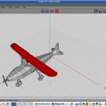
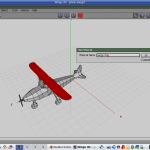
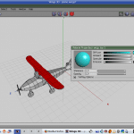
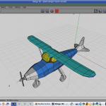
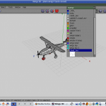
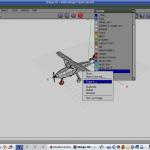
Fire up Wings 3D and open the plane model created in last month’s article. Once the model is displayed in the viewport, begin by selecting the polygons that form the top of the wings of the plane, as shown in Figure 1. To assign a new ‘material’ to the selected polygons, click the RMB (right mouse button), and choose the Material — New option in the New Material dialogue. Name it ‘wings top’, as shown in Figure 2.
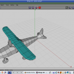
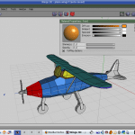
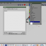
You will have the Material Properties dialogue come up. Go to the Diffuse button and change the colour (see Figure 3). After you are satisfied, click OK. Tap the space bar to de-select the polygons. You will observe that the top polygons have the colour you chose, and a distinct identity, as seen in Figure 4.
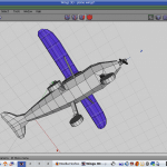
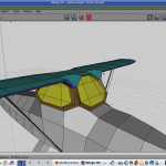
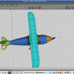
Now let’s move on to the lower part of the wings. Select the faces that form the lower part of the wings (including the edges of the wings that are left out). Apply a new material to them, giving the material a new colour, and therefore a distinct identity. Be sure you apply a colour that’s different from the other set of polygons. Figure 5 shows you the lower part of the wings with a different colour. Likewise, for the windows and frames, select them and assign a different identity to them. Figure 6 shows what the result might look like.
Now we come to the body of the plane. Select the polygons that form the central body of the plane, leaving out the tail, and the part in front of the cockpit, forming the nose of the plane. Once the selection is made, provide a distinct diffused colour to those faces, as demonstrated in Figure 7.
Select the faces that form the nose of the plane, and give them an identity, as shown in Figure 8. Figure 9 shows the tail after it is given a material ID.
After this, select the faces that form the propeller, and provide them with a separate identity, as shown in Figure 10. In the same fashion, assign separate materials to the rest of the plane.

The Outliner
After assigning distinct identities to all the parts of the plane, open the Outliner to see the names and colours of the materials you have created so far (it is accessible from the Window menu). Figure 11 shows the Outliner with the various materials I have created for the plane.

Unwrapping
As mentioned earlier, assigning separate materials to the various parts of the plane makes the process of unwrapping easier. Now, you do not have to select individual faces again, but from the Outliner, can right-click on a material and choose the Select menu option to select the whole of the named part.
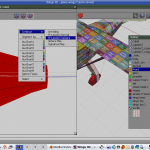
Begin with the material of the ‘body’ (the polygons that form the body of the plane). In the Outliner, right-click this material, and choose Select. The body of the plane turns red, indicating that the body is now selected. Next, right-click the selected body of the plane, and choose the UV mapping — Direct option.
A UV mapping window opens up, giving you the following options: Unfolding, Projection Normal, Projection Camera, Sphere map and Cylindrical map; so continue. Depending on how you want to paint the plane, choose the type of unwrapping. If you are unsure, simply select the Unfolding entry. An AutoUV window opens to show the part that is unwrapped and ready to be turned into a texture file.
However, do not be in a hurry. Before we actually get down to painting the plane, unwrap and place all the unwrapped maps away from each other, to avoid overlapping and confusion later on. As you unwrap, part by part, keep the parts separate. Later, you could rotate and scale the parts individually, before bringing them back to the highlighted square — which is where your texture map will be actually created.
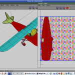
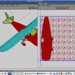
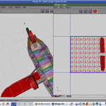
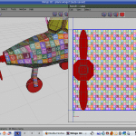
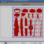
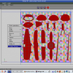
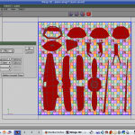
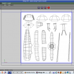
Figures 12 to 20 show you how the unwrapping was done, part by part, and how all the unwrapped parts were brought together to the central square, where the texture map will be generated.
Creating the texture and saving it
Once you have unwrapped all the different parts of the plane, scale them, rotate them, and arrange them in the central square, which you can save as your texture file. A look at Figure 20 shows how all the unwrapped segments are brought together.
Figures 21 to 23 show the process of saving the texture to a file. Open the Outliner, right-click the entry that says cube1_auv, and export it to a file (the file format could be whatever is convenient to you, the artist). The default file name for the texture is usually cube1_auv in case the basic geometry used was a cube, and the default format is BMP.
Now, let’s move to the GIMP to paint the texture.
Painting the texture and applying it
Before firing up the GIMP, a few words about it. Of late, the GIMP has developed a lot, especially with versions 2.6 and later. It is frequently compared to Photoshop, and is fondly called “Photoshop for free”; mind you, this is not an exaggeration! The GIMP can perform all the functions that Photoshop can; it is only a bad carpenter who blames his tools.
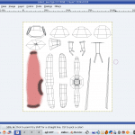
Start the GIMP, and open the BMP texture file. Start painting the texture, according to your whim and fancy, as I have done (look at Figures 24 to 26). Figure 25 shows a test render from my initial painting.
The steps for importing the painted BMP image into Wings 3D are simple. Just open the Outliner and right-click the texture that you made external and saved as a BMP file.
Click the Refresh option. The texture shows up right there in the Outliner. If you want the texture to be visible in your Wings 3D viewport, look for the Make Internal option and click it. You will see your plane textured, with the 2D texture file wrapping your 3D model.
Note: Your texture will not show up if you have not provided a diffused material before mapping your object.
You can render the model (for preview/testing) in Wings 3D itself, using OpenGL, the default rendering engine. You can also get a render preview in Blender, or any other 3D application of your choice, provided you export the model as a Wavefront object, which is universally accepted.

Figure 27 shows you the final rendering of the plane, after some more painting of the texture map. So, that is it, folks! Here ends the brief tutorial on mapping and texturing the plane that we created in our first tutorial published in October 2010.






















[…] flattened to position as wheels That’s all for the free-form modelling, folks. I will continue the UV mapping in the next issue.Figure 51: The final airplaneRelated Posts:Learn to Animate with Blender, Part 1: Modelling the […]