

This hands-on tutorial with a Raspberry Pi Pico microcontroller board will get you started on your IoT journey.
The Internet of Things (IoT) touches every aspect of our lives today. We can keep an eye on our home from hundreds of miles away through smart security cameras, while home assistant devices like Alexa obediently follow our commands to control our entire home. Every corner of our home or workplace has these tiny but powerful intelligent devices that create a whole automated system to provide a comfortable life.
Recent advances in open hardware and software standards-based systems have helped replace pricey and complicated embedded systems. The Raspberry Pi (RPI) Foundation has designed many general-purpose single board, low power and cost-effective hardware systems in the last few years to help create powerful IoT systems with a fraction of the effort and cost involved earlier. Millions of intelligent devices around the world are already using RPI hardware for modern IoT usage. So let’s jump onto this rocket ship of IoT too.
The tools and examples used in this brief tutorial are tested on Ubuntu 18.04 LTS on an AMD64 laptop and the latest Raspberry PI OS on RPI4, respectively. But everything should work on macOS and Windows too as the official tools are provided for those as well.
First encounter with PI Pico
Raspberry PI Pico 1 / 2 are generation 1 and 2 families of microcontroller boards with system-on-chip (SoC) based on ARM dual core RP 20240/2350 processors. Both families have boards with wireless LAN and Bluetooth connectivity too. You should be able to buy a Pico 1 board from a Raspberry Pi reseller in your country at a price of roughly
` 300 to ` 400 through the Raspberry Pi official website.
Remember that when you buy a board through reseller websites, if you see a letter H added after Pico 1 / 2 it means the header is soldered on the board. The board with header could be inserted at various places to control and interact with more external hardware components. And when you see the letter W appended after your Pico 1 / 2 series it indicates boards with wireless capabilities. The Pico 2 family is just an upgrade over Pico 1, with roughly double the RAM and faster cores, etc.
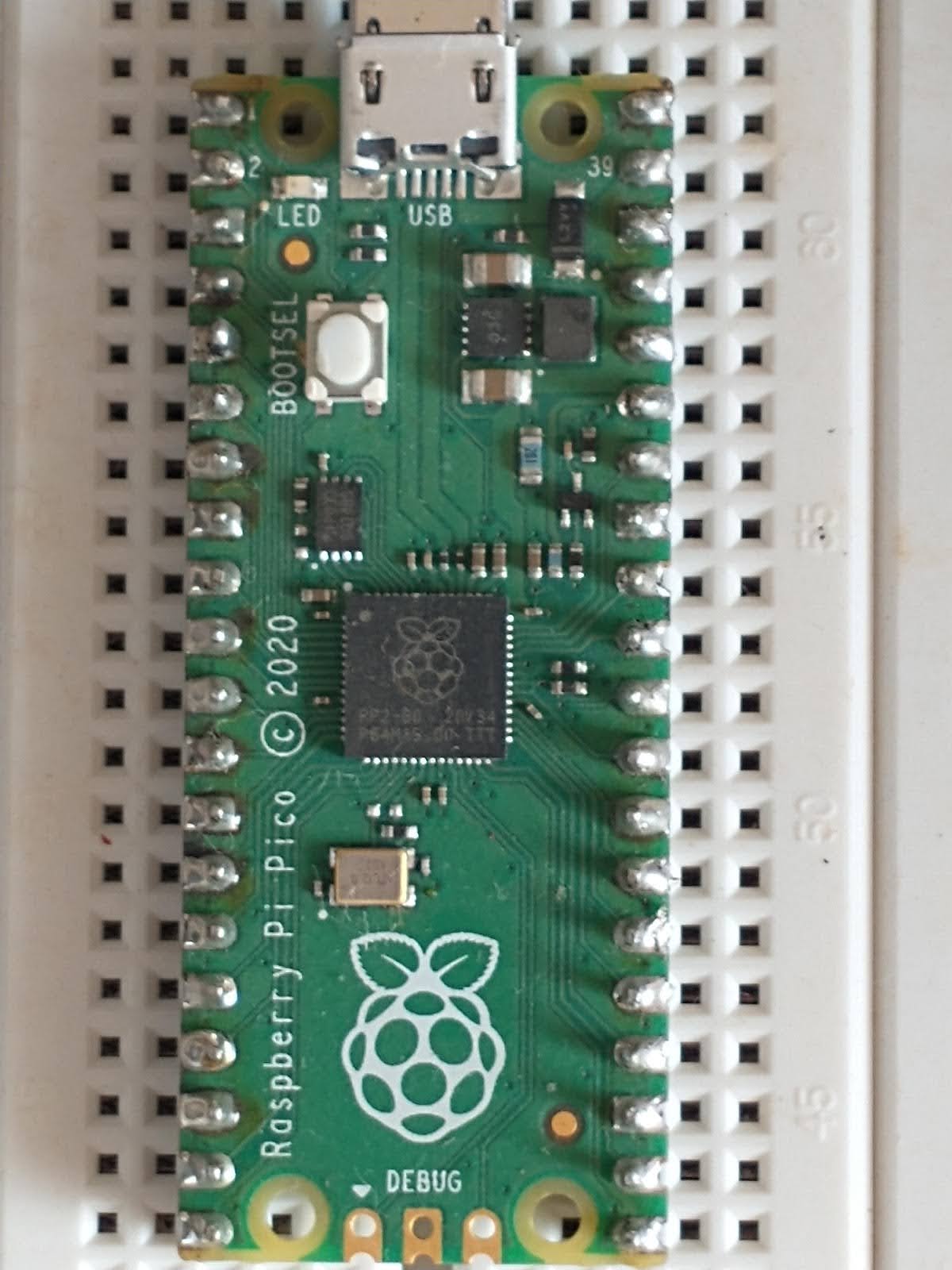
We’ll use the Pico 1 series board in this article to get started with the necessary fundamentals to quickly embark on our IoT journey. We don’t need any external electronic component, except a micro USB to USB cable to experiment with the Pico code snippets given in this section. Your Pico board should look like what’s shown in Figure 1 with important components like a USB port to program/power, onboard LED, BOOTSEL button, and a big black microcontroller chip in the middle clearly visible on it. Don’t worry if you can’t understand a few of the terms used in this section. Just follow along and you’ll be able to correlate with most of the things.
Now let’s set up the software to program our Pico 1 board. First, download the necessary firmware for Pico from the MicroPython download page link provided in the References section at the end of this article. Next, connect the USB cable to your computer, and press and hold the BOOTSEL button (visible in Figure 1) while inserting the cable into the micro USB port of the Pico board. You should see the Pico board mounted as a USB device in your computer. Just copy the downloaded UF2 firmware to the mounted Pico drive. The UF2 file will disappear from the mounted Pico drive once programming of the new firmware is complete. Now your Pico device will reset automatically and be ready for use.
Finally, we just need a Thonny Python IDE to interact with your Pico board, and program that for various IoT activities. You’ll find Thonny already installed on your Raspberry Pi OS if you are using an RPI single board computer. There are multiple methods to install Thonny on various operating systems. I prefer the following command to set up Thonny in an isolated manner so that it does not interfere with an existing Python installation on a GNU/Linux system:
bash <(wget -O - https://thonny.org/installer-for-linux)
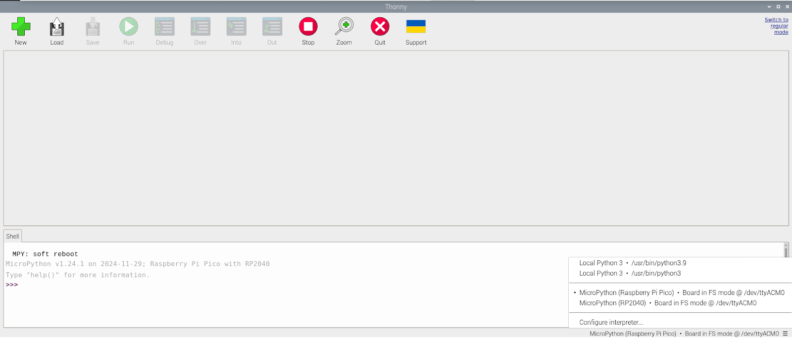
Just follow along and you’ll have Thonny installed with its binaries and its uninstaller under the ./apps/thonny/bin/ directory path. The installer should also create a menu item in your desktop system. Otherwise, execute the command apps/thonny/bin/thonny to launch it. Thonny is intelligent enough to detect your Pico board is connected and ready to program, as shown in Figure 2. You can also configure Thonny through the ‘Configure interpreter’ menu item in the right bottom side of the IDE.
The Pico board has an LED (clearly visible in Figure 1) connected to its programmable input output pin 25. As indicated by the name itself, the Pico board has multiple programmable pins to interact with external or internal devices to build numerous IoT projects. Just click on new (green button with + icon) in your Thonny IDE and enter this Python code there:
# onboard LED blink code
from machine import Pin
from time import sleep
pled = Pin(25, Pin.OUT)
pled.on()
sleep(1)
pled.off()
Now just hit the Run button on the Thonny IDE and you should see the LED on your Pico board light up for a second. Congratulations! You have started your IoT journey with the RPI Pico board. The logic of the MicroPython code shown above is simple: we set the GPIO pin 25 as an output pin, make the voltage high to ‘on’ the onboard LED and ‘off’ it after a delay to witness the LED glowing up. You can replace the pin number 25 provided in the pin constructor with the string ‘LED’ too to achieve the same result. You can also use the functions value(1) and value(0) instead of on() and off(), respectively, to make the voltage on the onboard LED pin high and low.
Let’s make the project more interesting by introducing a loop that will make the onboard LED blink continuously. The code for this is:
# onboard LED flashing code
from machine import Pin
from time import sleep
pled = Pin(“LED”, Pin.OUT)
while True:
pled.toggle()
sleep(1)
Now click on the Run button and the onboard LED should flash continuously until you hit the Stop button in the IDE. Feel free to experiment with decimal shorter values in sleep() as that gives a nice flashing effect. The logic of the code is self-explanatory: we’re running in an infinite loop with the onboard LED toggling ‘on’ to ‘off’ and vice versa on each run with a delay.
Let’s now work with an onboard hardware timer available on the Pico board to flash the onboard LED. Stop the existing code running in the IDE and run the code shown below to flash the LED through the onboard timer:
# h/w timer based LED flash
from machine import Pin, Timer
led = Pin(“LED”, Pin.OUT)
tim = Timer()
def tick(timer):
global led
led.toggle()
tim.init(freq=10, mode=Timer.PERIODIC, callback=tick)
The logic of the code is simple: a hardware timer on the Pico microcontroller is periodically invoking the onboard LED toggling. You can use a period=<time in milliseconds> in init() instead of freq and the timer. The timer runs in the background to invoke tick(…) at periodic intervals only. This code is non-blocking, and you’ll see a MicroPython prompt in the Thonny IDE to enter more code.
Wouldn’t it be nice to see the onboard LED blink in a fading up/down manner, for a change? The Pico board has pulse width modulation functionality for that. The code given below, taken from official Pico-MicroPython examples, makes the onboard LED blink in a fading mode:
# PWM based LED fading

import time

from machine import Pin, PWM

# Construct PWM object, with LED on Pin(25).

pwm = PWM(Pin(25))

# Set the PWM frequency.

pwm.freq(1000)


# Fade the LED in and out a few times.

duty = 0

direction = 1

for _ in range(8 * 256):

duty += direction

if duty > 255:

duty = 255

direction = -1

elif duty < 0:

duty = 0

direction = 1

pwm.duty_u16(duty * duty)

time.sleep(0.001)
The Pico board has analogue-to-digital converters to measure analogue signals and convert them to digital numbers to hand over to the microcontroller for processing in multiple ways. There is also a temperature sensor on the microcontroller chip connected to an ADC channel to report its temperature. This sensor gives a rough idea about the temperature of the environment the Pico board is being kept in. Let’s run the code given below, taken from official Pico-MicroPython examples, to see the temperature sensor in action:
# Temperature Sensor reading
import machine
import utime
sensor_temp = machine.ADC(4)
conversion_factor = 3.3 / (65535)
while True:
reading = sensor_temp.read_u16() * conversion_factor
# The temperature sensor measures the Vbe voltage of a biased bipolar diode, connected to the fifth ADC channel
# Typically, Vbe = 0.706V at 27 degrees C, with a slope of -1.721mV (0.001721) per degree.
temperature = 27 - (reading - 0.706)/0.001721
print(temperature)
utime.sleep(2)
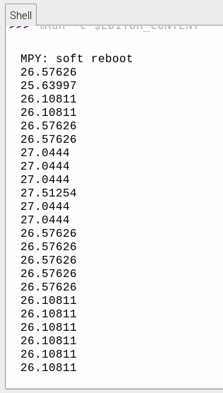
For a quick verification, just put your finger on the microcontroller chip (shown in Figure 1) and you’ll see the temperature reported increasing a bit. Removing your finger from the chip settles the temperature to lower values again. Figure 3 shows temperature readings as read in the Thonny IDE shell on my end.
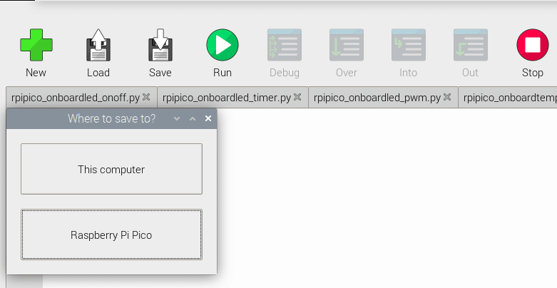
Last but not the least, you can program the Pico board to run your code every time when powered up. Once you finalise your MicroPython code after testing, just hit the Save button in your Thonny IDE and save your code as main.py by clicking the Raspberry Pi Pico button in the Where to save to? dialogue box, as shown in the screenshot in Figure 4.
Now onwards, your faithful RPI Pico board will start running the MicroPython code provided in main.py whenever it’s powered up. Isn’t that great?
Real-world use of the PI Pico board
The RPI Pico has multiple GPIO pins covering various kinds of hardware interfaces as shown in Figure 5. You can experiment with these multiple GPIO pins to create more interesting functionalities using some external electronic components. You need an RPI Pico board with header pins, a breadboard, some resistors, some LEDs, and some jumper wires for connections. You’ll be able to buy the additional components online or from a local electronics shop roughly within Rs 100.
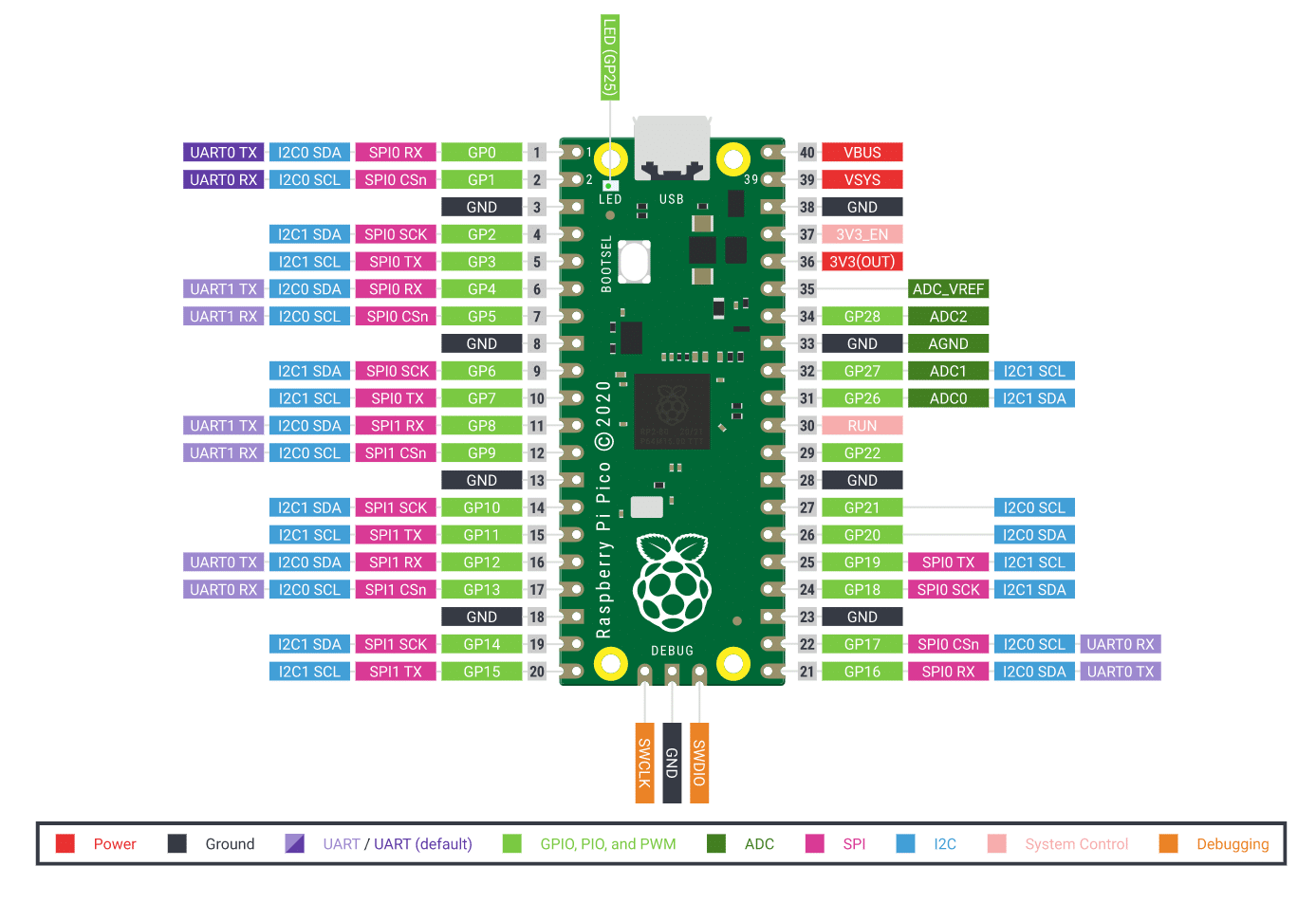
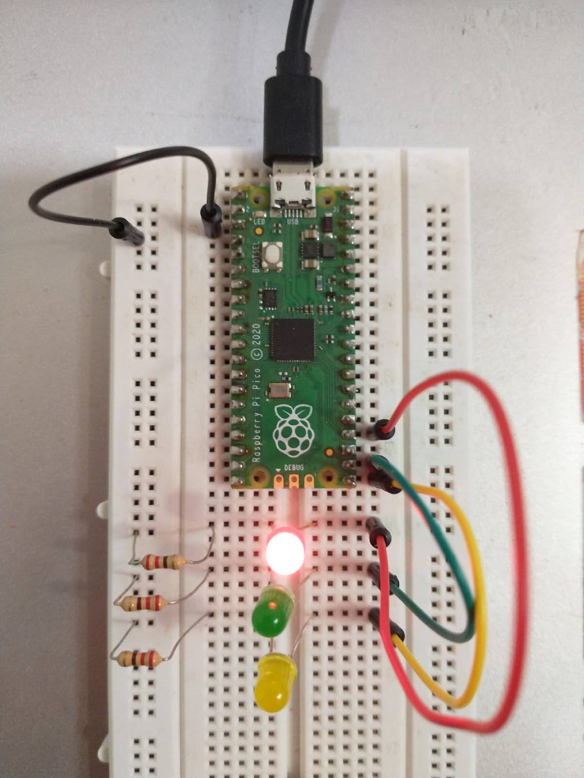
The code shown below is extending the single onboard LED flashing example to multiple external LEDs. Just wire the LEDs and resistors with jumper wires on a breadboard, run the code and you should see your Pico board driving external LEDs in the form of three LEDs in a traffic light pattern. Figure 6 shows the wired circuit of the traffic light external LEDs. The logic of the code is simple: configure three GPIO pins (choose from GPIO pin numbers shown in Figure 5) for driving the different colours of external LEDs, ensuring only one colour LED is ‘on’ at a time with a delay in between.
# external LEDs Traffic Light

from machine import Pin

from time import sleep

rled = Pin(18, Pin.OUT)

gled = Pin(17, Pin.OUT)

yled = Pin(16, Pin.OUT)


def stoponred():

global rled, gled, yled

rled.on()

gled.off()

yled.off()


def gongrn():

global rled, gled, yled

rled.off()

gled.on()

yled.off()


def readyonylw():

global rled, gled, yled

rled.off()

gled.off()

yled.on()


while True:

readyonylw()

sleep(2)

stoponred()

sleep(5)

gongrn()

sleep(5)
Please note that the Pico board has multiple pins to supply the necessary voltage to drive external electronic components like LEDs, etc. Once programmed through the Thonny IDE on your computer, you can also power up your Pico board independently through a single battery of 5V (or 3 x 1.5V batteries) connected through a micro-USB cable.
The low cost, power-efficient and versatile Raspberry Pi Pico boards have really opened the way for everyone to begin their IoT journey. We have just scratched the surface of the great IoT capabilities provided by the RPI Pico board to get you quickly started with it. Do explore the vast array of real-world projects available freely on the internet, as there is already a great open source ecosystem around it for you to create some breathtaking IoT systems.


