This article is about how to create an Arduino library and the opportunities in open source programming with the Arduino IDE. It will also show you how to interface a temperature sensor LM35 using your own library file.
Before we start speaking about this really cool thing called a custom library design, let us first discuss a few fascinating ideas related to open source programming and the basics of the Arduino IDE. The article assumes that the readers have a basic knowledge of electronics, and are aware of Arduino and the related sensors.
Open source programming and hardware
A few parameters for a programming language to be declared as open source are:
- The source code must be open and accessible
- It should be freely redistributable, yet the integrity of the author’s source code should be maintained
- Its licence must not restrict other software
- No discrimination against fields of endeavour
Many large institutions have sprung up to support the development of the open source movement, including the Apache Software Foundation, which supports Apache Hadoop and the open source HTTP server, Apache HTTP. The open source initiative is not only limited to engineering but extends to non-engineering areas too, including medicine, law and order, fashion design, etc. And the concept of ‘openness’ now encompasses hardware too.
A few examples of open source hardware initiatives are:
- Openmoko — a family of open source mobile phones, including the hardware specification and the operating system.
- Arduino — a microcontroller platform for embedded system designers.
- GizmoSphere — an open source development platform for the embedded design community.
- Simputer — an open hardware handheld computer, designed in India.
- LEON: A family of open source microprocessors distributed in a library with peripheral IP cores, open SPARC V8 specifications, and implementable under the GNU GPL.
- Tinkerforge — a system of open source stackable microcontroller building blocks.
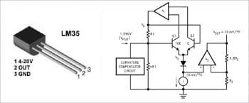
LM35 temperature sensor
The LM35 is a precision integrated circuit (IC) temperature sensor whose output voltage is directly proportional to the temperature (10 mv/ °C). The LM35 generates a higher output voltage than thermocouples and may not require the output voltage to be amplified. It does not require any external calibration or trimming, and maintains an accuracy of +/-0.4°C at room temperature and +/-0.8°C over a range of 0°C to +100°C. The scale factor is .01V/°C; it draws only 60 micro amps and possesses a low self-heating capability.
There are two transistors in the block diagram above — one has ten times the emitter area of the other. This means it has one-tenth of the current density, since the same current is going through both transistors. This causes a voltage across the resistor R1 that is proportional to the absolute temperature, and is almost linear across the range. The amplifier A1 ensures that the voltage at the base of the left transistor (Q1) is proportional to the absolute temperature by comparing the output of the two transistors. The amplifier A2 converts absolute temperature in Kelvin into either Fahrenheit (LM34) or Celsius (LM35). The ‘i’ in the block diagram is a constant current source circuit. The resistors R1 and R2 are calibrated in the factory to produce a highly accurate temperature sensor.
Arduino IDE
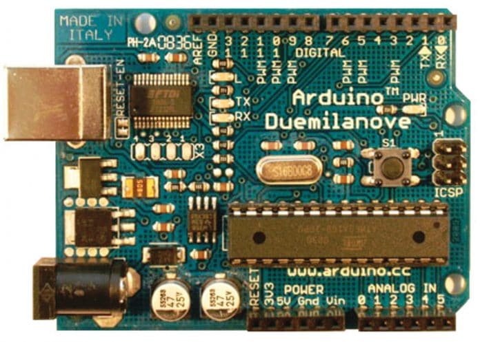
Arduino is an open hardware development board that can be used to design and build devices for use in everyday life. It is a physical computing platform based on a simple I/O board. A development environment can be used to develop standalone interactive objects or can be connected to software running on a computer. An Arduino board consists of an Atmel AVR microcontroller (ATmega328, ATmega168 and ATmega8 versions) and supporting hardware modules to facilitate programming and incorporate it into other circuits. One of the main features of this IDE is that the microcontroller is pre-programmed with a bootloader, so an external programmer is not necessary.
At a conceptual level, all boards are programmed over an RS-232 serial connection. Current Arduino boards include the USB-to-serial adapter chips such as the FTDI FT232. The Arduino board exposes most of the microcontroller’s I/O pins for use by other circuits. The Diecimila (another kind of Arduino board), for example, provides 14 digital I/O pins, six of which can produce PWM signals, and six analogue inputs. The Arduino boards available in the market are the Arduino Uno, Nano, Mega, Leonardo, Due, etc. The main differences between these are the controller used, and the total number of output pins and memory available for programming. We can choose particular boards according to the application and user requirements.
The core Arduino developer team includes Massimo Banzi, David Cuartielles, Tom Igoe, Gianluca Martino, David Mellis and Nicholas Zambetti.
Writing one’s own Arduino library
Libraries are files written in either C or C++, which provide the sketch/source code with extra or common functionality. The library file has three different file formats — *.cpp, *.h and one txt file that contains the different keywords used in library creation. The *.h file should contain the header files and *.cpp will hold the programming for that particular library.
In this example, our library EFYLM35 has EFYLM35.cpp, EFYLM35.h, and keywords.txt files. After writing these three files, they are placed in a zip file. To use a prebuilt existing library in our Arduino program, go to the Sketch menu on the IDE, choose Import Library and pick from the libraries available as EFYLM35. That will insert our library design #include EFYLM35.h and inbuilt Arduino IDEs #include Arduino.h at the top of the sketch along with the imported header file. These statements make the public functions and constants defined by the library available to our sketch. They also signal the Arduino IDE to link that library’s code with our code when it is compiled or uploaded. Because libraries are uploaded on the board with our sketch, they increase the amount of space used by the ATmega8 on the board. If we no longer need a particular library, simply delete its #include statements from the top of our code. This will stop the Arduino IDE from linking the library and reduce the amount of space used on the Arduino board.
The basic design steps for a user library on the Arduino IDE are listed below.
Step 1: The basic sketch for the library is written and the code layout is as follows:
#include <EFYLM35.h> //The custom made library for LM35class EFYLM35 {Statements} //declaring EFYLM35 class objectsvoid setup () {EFYLM35.initial(); //initializing the class definition}void loop () {EFYLM35.proceed()}; //things to at every loop iteration |
In the above code, function initial () is for initialising the variables (ports, etc) and the proceed () function is for some operational work at each looping cycle. Now make a list of all the input and output parameters we need. It’s time to step up and write our own Arduino library for the above operation. Arduino can also be built up in Java.
Step 2: To build the library, you are required to create two files—one with the extension EFYLM35.h and the second with the extension EFYLM35.cpp. In the EFYLM35.h (header file), the general structure is:
#ifndef __EFYLM35__ #define __EFYLM35__ //include types & constants of Wiring core APIclass EFYLM35 {public: //variables & functions, accessible outside of the class, and the class constructorEFYLM35(); //Default constructor of class EFYLM35void initial (); //define first functionvoid proceed (); //define second functionprivate: //private variables & functionsint input process (); //to process and draw conclusion from input}; //end of class xyz definition #endif //ending with end if |
Step 3: Save the above code as EFYLM35.h . The next step is to write your own .cpp file, which will contain the main() function, which is the driver function in a C++ program. Save this file as EFYLM35.cpp. Take both these files under one zip folder, and our own custom-made library.
#include<EFYLM35.h> //including the custom made header fileEFYLM35:: EFYLM35 () {//calling the default constructor}void EFYLM35:: initial () {//the body of initial () function //setup your sensor here}void EFYLM35::proceed() { //the body of the proceed(}int input_data= input_process(); } int EFYLM35::input_process() { //analogRead function}int EFYLM35:: EFYLM35 (int inputData) { //some complex stuff for LM35 conversion and output the results } |
The program
The types and constraints of the application program interface (API) are defined by #ifndef __EFYLM35__ and #define __EFYLM35__. To access the I/O functionalities of Arduino, we have to import the Arduino library by using the header file #include Arduino.h. Here, we have defined one class as the name EFYLM35. This class declares constructors and functions for reading the temperature value as well as to perform the averaging of a few samples to increase the accuracy. These functions are double read() and double read(int times), respectively.
The code for File 1 (the header file EFYLM35.h) is:
#ifndef __EFYLM35__#define __EFYLM35__#include “Arduino.h”class EFYLM35 {int _pin;public:EFYLM35(int pin);~EFYLM35();double read();double read(int times);};#endif |
The file EFYLM35.cpp will define the variables and functions used in the library. In this example, we declared that one port pin is in input mode, so the user can choose the pin number to measure the analogue value from LM35. This function will read the analogue value using the inbuilt 12A DC on Arduino IDE. The output of an LM35 can be connected directly to an Arduino analogue input. Because the Arduino analogue-to-digital converter (ADC) has a resolution of 1024 bits, and the reference voltage is 5V, the equation used to calculate the temperature from the ADC value is:
Temp = [((5.0 * sensorValue)) / 1024) * 100.0.] |
We can convert the read 12-bit digital value by multiplying with a constant of 0.48887585. The second function will ensure the accuracy of the temperature by taking the average of ‘N’ measurements.
The code for File 2 (the cpp file EFYLM35.cpp) is:
#include “EFYLM35.h”EFYLM35:: EFYLM35(int pin): _pin(pin) {pinMode(pin, OUTPUT);}EFYLM35::~ EFYLM35(){ }double EFYLM35::read() {int sensorValue = analogRead(_pin);double temperature = (sensorValue * 0.48875855);return temperature;}double EFYLM35::read(int times){int sum = 0;for (int i = 0; i < times; i++) sum += analogRead(_pin);double average = (sum * 0.48875855) / times;return average;}File 03: keywords.txt. This file is not necessary only for users’ information.EFYLM35 KEYWORD1read KEYWORD2 |
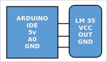
For simplicity in programming, we have not used any LCD interfacing. The temperature is viewed on the serial monitor of the IDE. Remember, you must choose the serial data transfer rate with 9600 bps, because our laptop or PC serial communication supported the RS 232C communication protocol. Here we have connected LM35 on the A0 channel and are taking the measurements five times.
#include <EFYLM35.h>void setup(){ Serial.begin(9600);}void loop(){EFYLM35 sensor1(A0); // Sensor connected to pin A0double temperature = sensor1.read(); //Returns temperature based on a single readingdouble avgtemperature = sensor1.read(5); //Returns average temperatureSerial.println(temperature);Serial.println(avgtemperature);} |
Final steps
1. Compile File 1 using C++ and save with extension EFYLM35.h.
2. Compile File 2 using C++ and save with extension EFYLM35.cpp.
3. Combine EFYLM35.h, EFYLM35.cpp and keywords.txt in a folder EFYLM35 and zip the folder using WinZip or WinRAR.
4. Open the Arduino IDE and go to Sketch > Include library > Add.ZIP library > Choose our zip folder EFYLM35. Now our library is added to the IDE.
5. Open a new file from the Arduino IDE and open Sketch > Include library > Choose the EFYLM35 library from the list. Now our header file will be included to that new sketch.
6. Write the program for interfacing the LM35 sensor using our own library (or use EFY_LM35.ino from the downloaded source code), and verify the output on the serial monitor.
The above steps and code help you to create and test your first library. You can try writing more complex libraries using the above process. Note: The complete code can be downloaded from https://www.opensourceforu.com/article_source_code/dec18/ard_lib.zip.


