In India, particularly in areas where teledensity is around 70 per cent and the literacy rate is quite low, voice can become an effective way of delivering services and information to the masses. Such a voice-enabled platform is backed by ASR (automated speech recognition) and TTS (text-to-speech) technology.
Traditionally, an IVR (interactive voice response) system is built on a DTMF (dual tone multi frequency) base input given by users. Whenever users call a customer care number, they hear an audio prompt and give inputs by pressing a number. This is known as the DTMF base input provided by users. But this has very limited functionality. Today, only 22 per cent of the people in the world have access to the Internet. DTMF based IVR systems also limit functionality. For example, AIIMS (All India Institute of Medical Science), New Delhi, has very long queues for the patient appointment system, often leading to hours of delay. AIIMS also has a Web portal for the patient appointment system but most of the patients are not IT literate, though they have access to telephones. So what do they do? They call the number 01126589999. After dialling, the system plays an audio prompt, asking callers to select Hindi or English by pressing a button. After this, the system asks the caller to enter the UHID number (old patients have a UHID card). When they enter this either via DTMF press or by speech, the system asks the caller: Which department do you want an appointment for? Say the department’s name. On receiving the reply, the system gives a time and date for the patient’s appointment. The patient also gets an SMS confirmation. This saves the organisation manpower in fixing the time for an appointment and increases organisational efficiency. Because AIIMS has more than 30 departments, users are asked to speak out the department’s name. Let’s now learn how to develop a speech based IVR system.
Hardware required for developing speech based IVR
a) PRI (primary rate interface) line: This is a line provided by telephone companies. Using the PRI line, we can get 30 calls per second, both incoming and outgoing, simultaneously. In India, PRI is delivered through the E1 Channel medium, which has a bandwidth of 2.048Mbit/s and 32 channels.
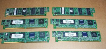
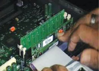
b) Cisco Router 2850 and above: In this router, the IOS (Internet operating system) is c2800nm-adventerprisek9-mz.151-4.M3.bin with PVDM card v3. PVDM stands for the packet voice DSP (digital signal processing) module. The PVDM card supports voice processing, just like the graphics card supports graphics. Please see Figures 1 and 2 for PVDM cards. Each PVDM v3 card supports 60 calls per second.
c) E1 card: In a Cisco router, there is one E1 card which should be installed for the termination of the PRI line to the router.
Note: A Cisco router is used for VXML browsers and MRCP clients.
Server requirements
Two core servers, with a minimum of 2GB of RAM, are sufficient to handle up to 30 calls per second.
Software requirements
a) VXML browser: This stands for Voice XML. It is like form in HTML. It collects data from speech-to-text and posts to the PHP page, or you can also post to the JSP page. It runs in the Cisco IOS browser. You can also install a separate VXML browser in CentOS, which is free and open source, like Voiceglue (a combination of Asterisk and open VXI). But I recommend that you use the Cisco IOS browser.
b) MRCP server: Media Resource Control Protocol (MRCP) is a communication protocol used by speech servers to provide various services (such as speech recognition and speech synthesis) to clients. Software for the MRCP server is Unimrcp, or you can use Nuance as the MRCP server. Here, the MRCP client will be the Cisco router. MRCP relies on another protocol, such as the Real Time Streaming Protocol (RTSP) or Session Initiation Protocol (SIP) for establishing a control session and audio streams between the client and the server.
c) Database: A MySQL server is used as the database server.
d) Web server: Apache is the Web server for content delivering systems.
e) Server side scripting language: PHP
f) Operating system: CENTOS 6.7
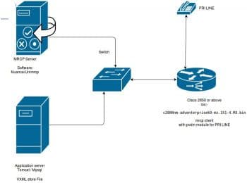
Please take a look at Figure 3. I will attempt to explain the technologies required to build a speech based IVR system.
Lets first set up the Cisco 2850 router for VXML browsing with a PRI line. Please find the configuration as given below for the Cisco router 2851. I have a PRI line pilot number 01206681400. The pilot number is a telephone number in the range of 6681400 to 6681430. If two or more than two people dial the number 6681400, then the system will connect the first one to 6681400, the second one to 6681401, the third to 6681402, and so on. But the caller will dial only the number 6681400.
To set up a router for receiving calls, the following prerequisites need to be in place:
a) IOS version: c2800nm-adventerprisek9-mz.151-4.M3.bin
b) E1 card
c) PVDM Card v3
Configuring the router
To do this, we have to focus on three steps:
a) Setting up the controller
b) Creating an application service
c) Dial-peer
I am assuming that you know how to set up a router with an IP address and remote access, and are able to define the route.
Please tale a look at the configuration given below:
Building configuration...Current configuration : 9165 bytes!! Last configuration change at 18:35:54 UTC Wed Dec 16 2015version 15.1service timestamps debug datetime msecservice timestamps log datetime msecno service password-encryption!hostname livedigital!boot-start-markerboot system flash:c2800nm-adventerprisek9-mz.151-4.M3.binboot-end-marker!!logging buffered 128000enable secret 5 $1$dIX2$/3T6ABkfIVVRTXUbC6Ub60!no aaa new-model!network-clock-participate wic 0network-clock-participate wic 2!dot11 syslogip source-route!!ip cef!!!ip host vxml_content 192.168.3.180!isdn switch-type primary-niisdn voice-call-failure 0!!trunk group 26max-calls any 30!!trunk group 20max-calls any 30preemption enablepreemption tone timer 4!!applicationservice trydtmf http://192.168.3.180/voice/tryDtmf.vxml!!mrcp client session history records 10mrcp client rtpsetup enablecrypto pki token default removal timeout 0!!!!license udi pid CISCO2851 sn FHK1324F0GDarchivelog confighidekeys!redundancy!!controller E1 0/0/0framing NO-CRC4pri-group timeslots 1-31trunk-group 26 timeslots 1-31!translation-rule 5!interface GigabitEthernet0/0ip address 192.168.3.103 255.255.255.0duplex autospeed auto!interface Serial0/0/0:15no ip addressencapsulation hdlcdialer pool-member 2isdn switch-type primary-niisdn integrate calltype allno cdp enable!control-plane!!voice-port 0/0/0:15!!mgcp profile default!!dial-peer voice 6681400 potsservice trydtmfincoming called-number 668141direct-inward-dialport 0/0/0:15forward-digits all!!!line con 0line aux 0line vty 0 4password airtelrouterlogintransport input all!scheduler allocate 20000 1000end |
First of all, to set up the controller, you should participate in the network clock for port utilisation. The command is:
#network-clock-participate wic 0 |
But some of the higher versions may not run this command first. You should select the card type E1. Here is the command:
#card type e1 0 0 |
Next, to set up the controller interface, enter the following command:
#isdn switch-type primary-ni |
The following command is for changing analogue signals to digital:
#trunk group 26#max-calls any 30 |
The following command is for use later on.
controller E1 0/0/0framing NO-CRC4pri-group timeslots 1-31trunk-group 26 timeslots 1-31! |
Here, Controller E1 0/0/0 is the interface name of the controller aligned with the first port. In India, framing NO-crc4 is the setting advised by most of the operators.
Pri-gorup timeslot 1-31 allocates 30 channels in one PRI line.
interface Serial0/0/0:15no ip addressencapsulation hdlcdialer pool-member 2isdn switch-type primary-niisdn integrate calltype all |
The above command interface Serial0/0/0:15 is for serial interface for analogue communication. This serial port 0/0/0:15 is used in making dial-peers, and to convert all analogue calls to digital signals.
The next step is to make the application configuration. In the application menu, you have to define the path of the VXML file with service name. For example:
applicationservice trydtmf http://192.168.3.180/voice/tryDtmf.vxml! |
This service name trydtmf is used to make dial-peers. Now its time to create dial-peers.
dial-peer voice 6681400 potsservice name trydtmfincoming called-number 668141direct-inward-dialport 0/0/0:15forward-digits all |
The first line above is to create dial-peer voice 6681400 in any number assigned. You can also assign a name to it. pots (plane old telephone service) is for a PRI analogue connection and you can use VoIP if you are using a SIP connection.
The second line is service name trydtmf. This command is used to call the VXML file, where we have already defined the path of VXML in the application menu of the above commands.
incoming called-number 668141 |
The above command is for defining the phone number whenever a user calls 668141 from her/his phone. The system will play VXML content as defined by the developer.
direct-inward-dialport 0/0/0:15forward-digits all |
The three lines given above are of DTMF, port, and the call transfer facility.
This is all for the Cisco router set-up — for call termination and application. In the next article, I will explain how to start VXML programming, and how to set up an MRCP server for speech recognition and a text-to-speech server.
Queries may be posted at http://rulariteducation.blogspot.in/2015/12/how-to-setup-cisco-router-2850-for-vxml.html.












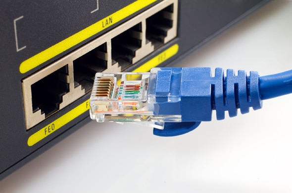


In telecommunications, IVR allows customers to interact with a companys host system via telephone keypad or by speech recognition, after which they can service their own inquiries by following the IVR in Brazil dialogue. It provides an aid for transferring calls to recorded playback. IVR in Brazil systems can respond with prerecorded or dynamically generated audio to further direct users on how to proceed.
get hosted ivr service and develop you won ivr by IVR GURU
http://www.ivrguru.in
how to set up an MRCP server for speech recognition and a text-to-speech server
how to set up an MRCP server for speech recognition and a text-to-speech server.
Extremely like your blog content the manner in which you put up the things… I’ve read the subject with incredible intrigue and certainly will adhere to your blog routinely for other extraordinary posts.
Thanks for sharing information on IVR Solution. I really appreciate it