This article goes deep into what really goes on inside an OS while managing and controlling the hardware. The OS hides all the complexities, carries out all the operations and gives end users their requirements through the UI (User Interface). GPIO can be considered as the simplest of all the peripherals to work on any board. A small GPIO driver would be the best medium to explain what goes on under the hood.
A good embedded systems engineer should, at the very least, be well versed in the C language. Even if the following demonstration can’t be replicated (due to the unavailability of hardware or software resources), a careful read through this article will give readers an idea of the underlying processes.
Prerequisites to perform this experiment
- C language (high priority)
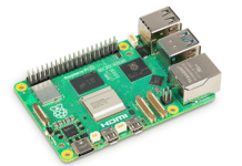
- Raspberry Pi board (any model)
- BCM2835-ARM-peripherals datasheet (just Google for it!)
- Jumper (female-to-female)
- SD card (with bootable Raspbian image)
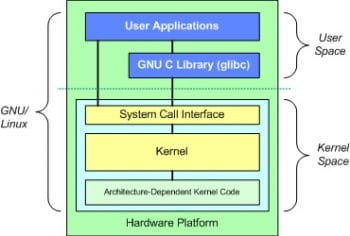
Here’s a quick overview of what device drivers are. As the name suggests, they are pieces of code that drive your device. One can even consider them a part of the OS (in this case, Linux) or a mediator between your hardware and UI.
A basic understanding of how device drivers actually work is required; so do learn more about that in case you need to. Lets move forward to the GPIO driver assuming that one knows the basics of device drivers (like inserting/removing the driver from the kernel, probe functionality, etc).
When you insert (insmod) this driver, it will register itself as a platform driver with the OS. The platform device is also registered in the same driver. Contrary to this, registering the platform device in the board file is a good practice. A peripheral can be termed a platform device if it is a part of the SoC (system on chip). Once the driver is inserted, the registration (platform device and platform driver) takes place, after which the probe function gets called.
Generic information
Probe in the driver gets called whenever a device’s (already registered) name matches with the name of your platform driver (here, it is bcm-gpio). The second major functionality is ioctl which acts as a bridge between the application space and your driver. In technical terms, whenever your application invokes this (ioctl) system call, the call will be routed to this function of your driver. Once the call from the application is in your driver, you can process or provide data inside the driver and can respond to the application.
The SoC datasheet, i.e., BCM2835-ARM-Peripherals, plays a pivotal role in building up this driver. It consists of all the information pertaining to the peripherals supported by your SoC. It exposes all the registers relevant to a particular peripheral, which is where the key is. Once you know what registers of a peripheral are to be configured, half the job is done. Be cautious about which address has to be used to access these peripherals.
Types of addressing modes
There are three kinds of addressing modes – virtual addressing, physical addressing and system bus addressing. To learn the details, turn to Page 6 of the datasheet.
The macro __io_address implemented in the probe function of the driver returns the virtual address of the physical address passed as an argument. For GPIO, the physical address is 0x20200000(0x20000000 + 0x200000), where 0x20000000 is the base address and 0x200000 is the peripheral offset. Turn to Page 5 of the datasheet for more details. Any guesses on which address the macro __io_address would return? The address returned by this macro can then be used for accessing (reading or writing) the concerned peripheral registers.
The GPIO control application is analogous to a simple C program with an additional ioctl call. This call is capable of passing data from the application layer to the driver layer with an appropriate command. I have restricted the use of other GPIOs as they are not exposed to headers like others. So, modify the application as per your requirements. More information is available on this peripheral from Page 89 of the datasheet. In this code, I have just added functionality for setting or clearing a GPIO. Another interesting feature is that by configuring the appropriate registers, you can configure GPIOs as interrupt pins. So whenever a pulse is routed to that pin, the processor, i.e., ARM, is interrupted and the corresponding handler registered for that interrupt is invoked to handle and process it. This interesting aspect will be taken up in later articles.
Compilation of the GPIO device driver
There are two ways in which you can compile your driver.
- Cross compilation on the host PC
- Local compilation on the target board
In the first method, one needs to have certain packages downloaded. These are:
- ARM cross-compiler
- Raspbian kernel source (the kernel version must match with the one running on your Pi; otherwise, the driver will not load onto the OS due to the version mismatch)
In the second method, one needs to install certain packages on Pi. - Go to the following link and follow the steps indicated: http://stackoverflow.com/questions/20167411/how-to-compile-a-kernel-module-for-raspberry-pi
- Or, follow the third answer at this link, the starting line of which says, “Here are the steps I used to build the Hello World kernel module on Raspbian.”
I went ahead with the second method as it was more straightforward.
Testing on your Raspberry Pi
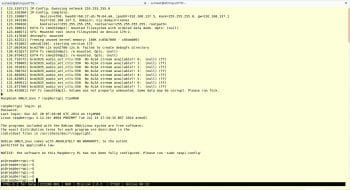
Boot up your Raspberry Pi using minicom and you will see the console that resembles mine (Figure 2).
- Run sudo dmesg C. (This command would clean up all the kernel boot print logs.)
- Run sudo make. (This command would compile GPIO driver. Do this only for the second method.)
- Run sudo insmod gpio_driver.ko. (This command inserts the driver into the OS.)
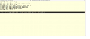
- Run dmesg. You can see the prints from the GPIO driver and the major number allocated to it, as shown in Figure 3. (The major number plays a unique role in identifying a specific driver with whom the process from the application space wants to communicate with, whereas the minor number is used to recognise hardware.)
- Run sudo mknod /dev/bcm-gpio c major-num 0. (The mknod command creates a node in /dev directory, c stands for character device and 0 is the minor number.)
- Run sudo gcc gpio_app.c -o gpio_app. (Compile the GPIO control application.)

Now lets test our GPIO driver and application.
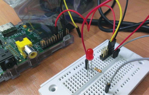
To verify whether our driver is indeed communicating with GPIO, short pins 25 and 24 (one can use other available pins like 17, 22 and 23 as well but make sure that they aren’t mixed up for any other peripheral) using the female-to-female jumper (Figure 4). The default values of both the pins will be 0. To confirm the default values, run the following commands:
sudo ./app -n 25 -g 1
This will be the output. The output value of GPIO 25 = 0.
Now run the following command:
sudo ./app -n 24 -g 1

This will again be the output. The output value of GPIO 24 = 0.
Thats it. Its verified (see Figure 5). Now, as the GPIO pins are shorted, if we output 1 to 24 then it would be the input value of 25 and vice versa.
To test this, run:
sudo ./app -n 24 -d 1 -v 1 -s 1
This command will drive the value of GPIO 24 to 1, which in turn will be routed to GPIO 25. To verify the value of GPIO 25, run:
sudo ./app -n 25 -g 1
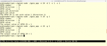
This will give the output. The output value of GPIO 25 = 1 (see Figure 6).
One can also connect any external device or a simple LED (through a resistor) to the GPIO pin and test its output.
Arguments passed to the application through the command lines are:
-n : GPIO number
-d : GPIO direction (0 – IN or 1 – OUT)
-v : GPIO value (0 or 1)
-s/g : set/get GPIO
The files are:
gpio_driver.c : GPIO driver file
gpio_app.c : GPIO control application
gpio.h : GPIO header file
Makefile : File to compile GPIO driver
After conducting this experiment, some curious folk may have questions like:
- Why does one have to use virtual addresses to access GPIO?
- How does one determine the virtual address from the physical address?
We will discuss the answers to these in later articles.


