


 Verilog, a hardware description language, is used to model electronic systems, and to design and verify digital circuitry at the register-transfer level of abstraction. It can also be used to verify analogue circuits and mixed signal circuits.
Computers now play a major role in every design field. The complexity of structures is so high that we can no longer think about doing things manually. This is the trend not only in electronics but in all spheres of engineering. Gone are the days when designers could verify their circuits on a breadboard. Today’s integrated circuits are so complex that they contain thousands of transistors on a single chip.
In the 1980s, designers felt the need for a language that could model digital circuits so that the circuit could be simulated and analysed. That’s how hardware description languages (HDL) came into being. In this article, I will introduce you to an open source Verilog simulation and synthesiser tool. It is assumed that the readers have some basic knowledge in Verilog programming.
Design flow
HDLs alone were not sufficient to reduce the workload on VLSI circuit designers. Soon, logic synthesis tools were developed, which could translate an HDL-based design into a schematic circuit.
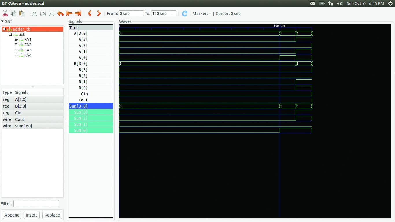
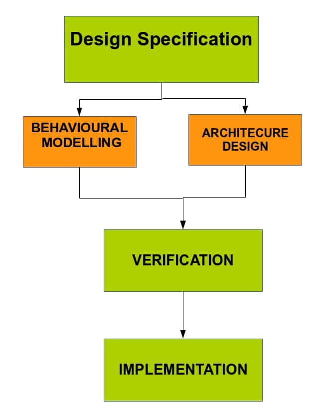 Figure 1 gives a brief idea about the process flow in VLSI IC design. First the requirements of the circuit to be designed are studied, and the designers prepare a behavioural model that will describe the functional requirements of the circuit. In the HDL, both behavioural and architectural details are taken care of. Then the logic synthesis tools convert the HDL to a gate level netlist.
Need for HDL
Hardware description languages differ from software programming languages because they include ways of describing the propagation of time and signal dependencies. With HDL, the designs are made at a very abstract level, which are independent of the technology that will be used for IC fabrication. This helps in the functional verification of the design and also in optimising it.
Verilog
Verilog was created by Phil Moorby and Prabhu Goel in 1984. It was invented as a simulation language and support for synthesis was only added afterwards. An IEEE working group was established in 1993 under the Design Automation Sub-Committee to produce the IEEE Verilog standard 1364. Verilog became IEEE Standard 1364 in 1995. The IEEE working group released a revised standard in March 2002, and it was known as IEEE 1364-2001. Significant publication errors marred this release, and a revised version was released in 2003, which was known as IEEE 1364-2001 Revision C.
VHDL
VHDL is an acronym for Very High Speed Integrated Circuit Hardware Description Language, which is a programming language used to describe a logic circuit by function, data flow behaviour or structure. The development of VHDL was initiated in 1981 by the United States Department of Defence.
Icarus Verilog compiler and GTKWave
Icarus Verilog or iverilog is an implementation of the Verilog hardware description language. It supports the 1995, 2001 and 2005 versions of the standard, portions of SystemVerilog and some extensions.
Icarus Verilog is available for Linux, Windows and Mac OS X. It is released under the GNU General Public License.
GTKWave is a fully featured GTK+ based waveform viewer, which is used to view the simulated output of the Verilog code.
Installation
These are the steps to install iverilog and GTKWave in Ubuntu.
sudo add-apt-repository ppa:team-electronics/ppa
sudo apt-get update
sudo apt-get install verilog gtkwave
An example
It is customary to start with ‘Hello World’. So given below is the code for a ‘Hello World’ program in Verilog.
module helloworld;
  initial
    begin
      $display("Hello, World");
      $finish;
    end
endmodule
Save this file as hello.v. Now run the following command to compile hello.v:
iverilog -o hello hello.v
The results of this are placed in the file ‘hello’, because the ‘-o’ flag tells the compiler where to place the compiled result. This file can be executed with the following command:
vvp hello
‘and it will run the program.
Verilog is not a language used for printing ‘Hello world’. So let’s take a look at a logic design program. Let us design a 4-bit full adder. A 4-bit adder will take two 4-bit values, A and B, and a carry in. The outputs will be a 4-bit sum and a 1-bit carry out.
Note: Readers are requested to read and understand digital electronics principles so as to figure out how adders and other digital circuits work.
The code for a 4-bit adder is as follows. Save it as adder.v
module half_adder(
    output S,C,
    input A,B
    );
xor(S,A,B);
and(C,A,B);
endmodule

module full_adder(
    output S,Cout,
    input A,B,Cin
    );
wire s1,c1,c2;
half_adder HA1(s1,c1,A,B);
half_adder HA2(S,c2,s1,Cin);
or OG1(Cout,c1,c2);

endmodule

module ripple_adder_4bit(
    output [3:0] Sum,
    output Cout,
    input [3:0] A,B,
    input Cin
    );
wire c1,c2,c3;
full_adder FA1(Sum[0],c1,A[0],B[0],Cin),
FA2(Sum[1],c2,A[1],B[1],c1),
FA3(Sum[2],c3,A[2],B[2],c2),
FA4(Sum[3],Cout,A[3],B[3],c3);

endmodule
We will need a test bench to simulate this code. A test bench is a program that will call an instance of our adder module, and it will supply the adder inputs to generate the output. Let us save this file as adder_tb.v
module adder_tb;
// Inputs
reg [3:0] A;
reg [3:0] B;
reg Cin;
// Outputs
wire [3:0] Sum;
wire Cout;
// Instantiate the Unit Under Test (UUT)
ripple_adder_4bit uut (
.Sum(Sum),
.Cout(Cout),
.A(A),
.B(B),
.Cin(Cin)
);
initial begin
// Initialize Inputs
A = 0;
B = 0;
Cin = 0;
// Wait 100 ns for global reset to finish
#100;
// Add stimulus here
A=4'b0001;B=4'b0000;Cin=1'b0;
#10 A=4'b1010;B=4'b0011;Cin=1'b0;
#10 A=4'b1101;B=4'b1010;Cin=1'b1;
end
initial begin
$dumpfile("adder.vcd");
$dumpvars;
end
endmodule
Now, in the terminal, cd to the folder containing adder.v and adder_tb.v, and then type the following command:
$ iverilog -o adder adder.v adder_tb.v
$ vvp adder
This should generate the adder.vcd file. Then type the following command:
$ gtkwave adder.vcd
This will open the GTKWave window and you will get a window similar to what’s shown in Figure 2.
Online Verilog simulator
An online C-to-Verilog converter
www.c-to-verilog.com is an online platform on which you can convert programs written in C language to Verilog. This is beneficial to those who are well versed in C but are not so sure about Verilog code. The FAQ section of the website has a few examples that demonstrate the features of c-to-verilog.com.
Icarus Verilog is one of the most popular Verilog simulators in the open source domain. There are many other proprietary software. Verilator is another open source simulator that can synthesise Verilog code to C++ or SystemC. It is up to the readers to further explore the world of logic design.
References
[1] Verilog HDL- A Guide to Digital Design and Synthesis
by Samir Palnitkar
[2] http://www.verilog.com/
[3] http://en.wikipedia.org/wiki/VHDL
[4] http://iverilog.icarus.com/


