Instruction Level Parallelism (ILP) technology is often used to improve the performance of embedded processors in application-specific domains like Digital Signal Processing. Today’s VLIW (Very Large Instruction Word) DSP architectures are specially designed to take advantage of ILP. This article aims to provide an insight into the technique behind Instruction Level Parallelism that will help compiler developers, in particular, to understand what ILP is, and how it can be designed while developing a compiler.
Instruction Level Parallelism (ILP) refers to the execution of two or more instructions in parallel — i.e., in the same instruction cycle. For example, consider the sample set of instructions for a hypothetical processor in Figure 1. R0, R1, R2 and R3 represent general-purpose registers, and AR0 represents the address register. So MOVE R0, [AR0]++ means that the contents of memory location AR0 have to be moved to register R0, and the address register AR0 has to be incremented.

Now, suppose that the hypothetical architecture under consideration supports parallelism of an arithmetic operation instruction and a transfer instruction (instructions ‘2’ and ‘3’ in Figure 1, also identified by in-line comments). We may execute these instructions in parallel, to achieve ILP, as shown in Figure 2.

Assuming that our hypothetical processor takes one instruction cycle and one word for any type of instruction, the reduction in the number of instruction cycles and code size with ILP is visible in Figure 3.

Internals of ILP: The algorithm
Note that we will restrict this article to achieve ILP within a single basic block only.

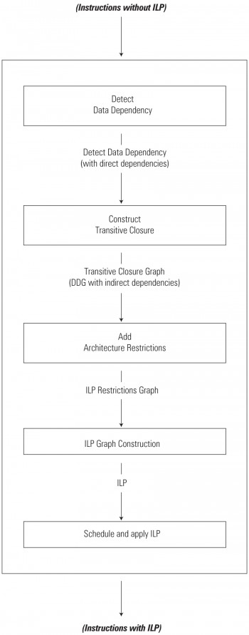
The ILP module is broken down into several sub-modules, as shown in Figure 4. The overall algorithm to achieve ILP is:
- Detect data dependencies
- Construct transitive closure
- Add architecture restrictions
- Construct the ILP graph
- Schedule and apply ILP
Each of these steps is explained in detail below. We use the following code block as the subject (to which we will apply the ILP algorithm, step by step):
1. MOVE R0, [AR0];2. ADD R1, R2, R2;3. MOVE R3, [AR1];4. ADD R4, R3, R1;5. ADD R3, R4, R4;6. SUB R3, R3, R4 |
Step #1: Detect data dependency
An Instruction J is said to be (directly) data-dependent on an Instruction I, if any of the following relationships exists between the two instructions:
- Data flow dependency
- Anti-dependency
- Output-dependency
Note: We also have control dependency, which involves more than one code block. However, since this article is restricted to achieving ILP within a basic block, we will not cover this dependency.
As illustrated in Figure 5, Instruction I is an instruction preceding Instruction J in the basic block.

Data flow dependency definition: An Instruction J is said to be data flow dependent on an Instruction I, if I defines an operand (variable/register) that is used by J.
For example, consider the following instructions in the example given below:
3. MOVE R3, [AR1]; --> I // defines "R3"4. ADD R4, R3, R1; --> J // uses "R3" |
Here, Instruction 3 “defines” register R3, which is used as a source operand in Instruction 4 — so we have a data flow dependency between Instructions 3 and 4.
Note: Unless stated explicitly, we have assumed that in our hypothetical architecture, the first operand of an instruction is the destination operand, and the remaining are source operands.
Anti-dependency definition: An Instruction J is said to be data anti-dependent on Instruction I, if I uses an operand (variable/register) that is redefined by J.
For example, consider these instructions:
3. MOVE R3, [AR1]; ; // "R3" defined4. ADD R4, R3, R1; --> I // Uses "R3"5. ADD R3, R4, R4; --> J // Redefines "R3" |
Here, Instruction 3 “defines” register R3, which is “used” as a source operand in Instruction 4. Then Instruction 5 redefines (or updates) R3. Thus, we have an anti-dependency between Instructions 4 and 5.
Output dependency definition: An Instruction J is said to be data output-dependent on an Instruction I, if I and J redefine the same operand (variable/register).
Look at the same example given above for anti-dependency. Register R3, defined in Instruction 3, is redefined in Instruction 5. Hence, we have an output dependency between Instructions 3 and 5.
As illustrated in Figure 5, ILP is restricted when we have dependency between instructions. If an Instruction J is dependent on an Instruction I, these instructions can not be combined in parallel.
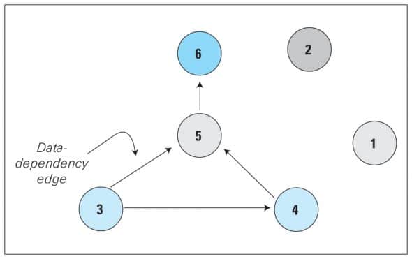
Data dependencies between instructions are graphically represented by a Data Dependency Graph (DDG), in which:
- Each node represents an instruction (of the basic block)
- The edges show the dependency between the instructions
Thus, for the given six instructions in our subject code block, the DDG will be as in Figure 6.

To build a DDG:
- Initialise the DDG with representations of the instructions.
- Traverse the instructions of the basic block one by one, and check for data dependencies (data flow dependency/anti-dependency/output dependency)
- As you find dependencies, update the DDG with directed edges depicting each of them.
Step #2: Compute transitive closure
Transitive closure takes as input the DDG prepared in the previous step, and its output is a Transitive Closure Graph (TCG). We need a transitive closure to determine the indirect dependencies between the instructions. We determine the indirect dependencies from the direct dependencies.
Given that G is an n-vertex digraph (directed graph) such as the DDG shown in Figure 6, we construct the transitive closure graph of the digraph G as another n-vertex digraph (let’s call it H) by adding edges to G, following this rule. In H, add an edge (i, j) directed from vertex i to j if, and only if, there is a directed path (of any length* — 1, 2, 3, …, n-1) from ‘i’ to ‘j’ in G. [*The number of edges in the path is referred to as the length of the path.]
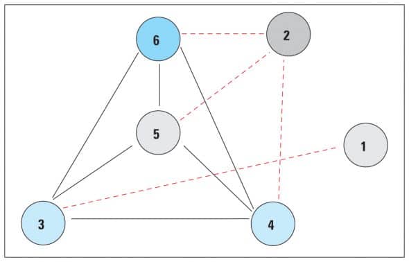
In Figure 6, the DDG shows that instruction 5 is dependent on Instruction 3 and Instruction 6 is dependent on Instruction 5. Thus, we have an indirect dependency between Instructions 3 and 6. So we add an edge between instruction Node 3 and instruction Node 6. Similarly, we have an indirect dependency between Instructions 4 and 6. We add these edges in the DDG, to obtain the TCG as shown in Figure 7 (the edges shown in red are the indirect dependency edges).

Step #3: Add architecture restrictions
Some processors may have some restrictions on which instructions can be combined in parallel. For example, we may not be able to combine two arithmetic ADD instructions in parallel. Similarly, we may not be able to combine branch instructions (like compare and jump) in parallel with any other instruction. Such restrictions are termed architecture restrictions.
Architecture restrictions may be represented by what I call an ILP Restriction Graph (IRG), which depicts which instructions cannot be combined in parallel. We obtain an IRG after adding architecture restrictions to the Transitive Closure Graph.
To build an IRG:
- Initialise the IRG with the TCG (i.e., copy the nodes and edges in the TCG, as is, to the IRG).
- Convert the graph to an undirected graph — i.e., remove any direction from the edges that are already present.
- Add the architecture restriction edges to the IRG — these are also undirected edges, making the IRG itself an undirected graph.
The IRG is an undirected graph because the direction of edges is not relevant. When we have an architecture restriction between any two instructions A and B, whether I say we have an architecture restriction between A and B, or between B and A, is immaterial.
Let’s walk through this, and convert our TCG (Figure 7) to an IRG. After converting the TCG to an undirected graph, we now add architecture restriction edges to the undirected TCG. In the above example, let’s say there is the architecture restriction that we cannot combine two arithmetic operation instructions in parallel. Similarly, assume that we cannot combine two transfer instructions in parallel. That means that we have an architecture restriction between the following instructions:
- Instruction 1 and Instruction 3
- Instruction 2 and Instruction 4
- Instruction 2 and Instruction 5
- Instruction 2 and Instruction 6
Thus, we add four new edges to the undirected TCG, to obtain the ILP Restriction Graph as shown in Figure 8. The architecture restriction edges are dashed lines shown in red.

Step #4: Construct the ILP graph
The ILP Graph (see Figure 9) shows all the possibilities of parallelism between instructions, and is the complement of the ILP Restrictions Graph obtained in Step 3.

The ILP graph shows that we have possibilities of parallelism between the following instruction pairs:
- Instruction 1 and Instruction 2
- Instruction 1 and Instruction 4
- Instruction 1 and Instruction 5
- Instruction 1 and Instruction 6
- Instruction 2 and Instruction 3
Step #5: Schedule and apply ILP
In the schedule and apply ILP step, we try to achieve the parallelism depicted in the ILP graph. Assume that our hypothetical architecture supports ILP of a maximum of two instructions in parallel. As we saw above, Instruction 1 shows the possibility of parallelism with any of the following instructions — 2, 4, 5 or 6. So which instruction should we pair with Instruction 1?
The selection of an ILP pair instruction is an important step, because it can have an impact on any further ILPs to be achieved. Let’s explore this practically with our subject code block.
Case A: Let’s attempt to combine Instructions 1 and 2 in parallel:
1. MOVE R0, [AR0]; ADD R1, R2, R2;3. MOVE R3, [AR1];4. ADD R4, R3, R1;5. ADD R3, R4, R4;6. SUB R3, R3, R4 |
The result is that no other ILP is possible now in the instruction set, because we have already utilised Instruction 2, which was a candidate for parallelism with Instruction 3. Now the ILP of Instructions 2 and 3 (as was shown by the ILP graph) can no longer be achieved. So, this case is a bad selection of instructions for parallelism.
Case B: We select Instruction 1 to be paired with Instruction 4:
1. MOVE R0, [AR0] ADD R4, R3, R1;2. ADD R1, R2, R2;3. MOVE R3, [AR1];5. ADD R3, R4, R4;6. SUB R3, R3, R4 |
Now, we can easily achieve the parallelism of Instructions 2 and 3, as well:
1. MOVE R0, [AR0] ADD R4, R3, R1;2. ADD R1, R2, R2 MOVE R3, [AR1];5. ADD R3, R4, R4;6. SUB R3, R3, R4 |
The selection of instructions for parallelism is a critical step. The idea is to select the instructions in such a way that the maximum ILPs are achieved. Since our goal is to reduce the number of instruction cycles as well as the code size, the more the ILPs we achieve, the better. Since Case B clearly yields more ILPs than Case A, this is our chosen case to maximise ILP.
References and further reading
Narsingh Deo: Graph Theory with Applications to Engineering and Computer Science
Sima, Fountain and Kacsuk: Advanced Computer Architectures — A Design Space Approach
Feature image courtesy: Alosh Bennett. Reused under the terms of CC-BY 2.0 License.


